OPD (OreSat Power Domain)
The OPD allows the C3 to turn other cards on or off, with the exception of the solar cards. The solar cards are directly powered off the output of their solar panels and not the batteries. Yes, the battery cards are also on the OPD, as the batteries will work regardless of whether the card is enabled or not. Enabling the battery card(s), allows for telemetry from the battery card; i.e.; voltage level, charge level, etc.
How It Works
Every card, other than the solar cards, has a MAX7310 to control giving power to the card. The MAX7310 is 8-pin GPIO expander with an I2C interface.
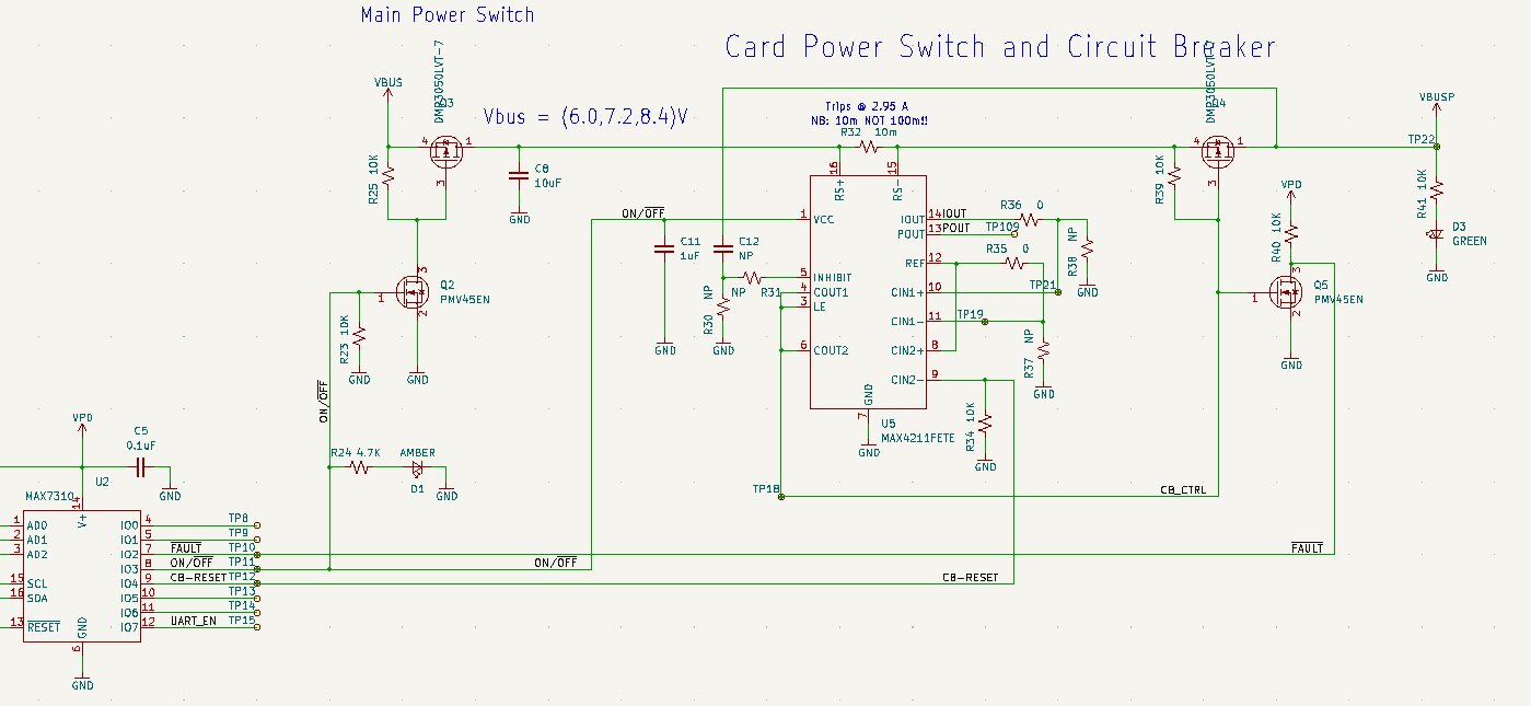
3 of the 8 pins are standardized on all cards to be for Not Fault, Enable, and CB Reset.
Not Fault Pin: Is an input pin. When it is High, the circuit does not have a fault; when it is low the circuit has a fault.
Enable Pin: Is an output pin. When set High, the card is enabled (powered on). When the pin is set Low, the card is disabled (powered off).
CB Reset Pin: The circuit breaker reset is an output pin. It can reset the enable circuit. When held high for a little while, it will hopefully clear the fault.
Note
Any pin that is not used is considered a test point and is set low.
OPD on STM32 Cards
On top of the standard 3 pins, the STM32-based cards also utilize pins for an I2C bootloader and enabling a UART connection.
I2C SCL Pin: Is an input pin. Used by I2C bootloader.
I2C SDA Pin: Is an input pin. Used by I2C bootloader.
Boot Pin: Is an output pin. When set high before being the Enable pin is set, will put the STM32 into bootloader mode.
UART ENABLE Pin: Is an output pin. When set high, the cards will be connected to the C3’s UART bus.
OPD on Ocatvo A8 Cards
On top of the standard 3 pins, the STM32-based cards also utilize pins for boot selection pin and enabling a UART connection.
Boot Pin: Is an output pin. When set high, the card will boot off of the eMMC; when set low, the card will boot off of the SD card.
UART ENABLE Pin: Is an output pin. When set high, the cards will be connected to the C3’s UART bus. This will allow the cards eMMC to be reflashed.
OPD State Machine
- class oresat_c3.subsystems.opd.OpdState(value)[source]
OPD subsystem states.
- DISABLED = 0
OPD subsystem is off.
- ENABLED = 1
OPD subsystem is on (no faults).
- FAULT = 2
OPD subsystem is on and has one or more faults.
- DEAD = 3
OPD subsystem is consider dead (too many faults in a row).
        stateDiagram-v2
    [*] --> DISABLED
    DISABLED --> ENABLED: Subsystem is enabled
    ENABLED --> DISABLED: Subsystem is disabled
    ENABLED --> FAULT: Subsystem has a fault
    FAULT --> ENABLED: Subsystem was reset and then fault cleared
    FAULT --> DISABLED: Subsystem is disabled
    FAULT --> DEAD: Subsystem failed to reset multiple time in a row
OPD Node State Machine
- class oresat_c3.subsystems.opd.OpdNodeState(value)[source]
OPD node states
- DISABLED = 0
OPD Node is off
- ENABLED = 1
OPD Node is on
- FAULT = 2
Fault input is set for OPD node
- DEAD = 3
OPD node is consider dead (too many faults in a row).
- NOT_FOUND = 255
OPD node is not found
        stateDiagram-v2
    [*] --> DISABLED: Node is found
    [*] --> NOT_FOUND: Node is not found
    NOT_FOUND --> DISABLED: Node is found
    DISABLED --> ENABLED: Node is enabled
    DISABLED --> NOT_FOUND: Node is lost
    ENABLED --> FAULT: Node has a fault
    ENABLED --> NOT_FOUND: Node is lost
    ENABLED --> DISABLED: Node is disabled
    FAULT --> ENABLED: Node was reset and then fault cleared
    FAULT --> NOT_FOUND: Node is lost
    FAULT --> DISABLED: Node is disabled
    FAULT --> DEAD: Node failed to reset multiple time in a row